Scenario:
VLAN 1 can communicate with VLAN 2 but VLAN2 cannot access VLAN 1. Both VLANS can access the internet.
DFL-210/800/1600:
Lan Interface: 192.168.1.1
VLAN1: 192.168.2.1
VLAN2: 192.168.3.1
DGS-3024:
Default VLAN--- VID-1---Ports 1-8
Vlan1 VLAN--- VID 2---Ports 9-24
Port 1 will be tagged and connected to the DFL-210/800/1600.
Setup of DGS-3024
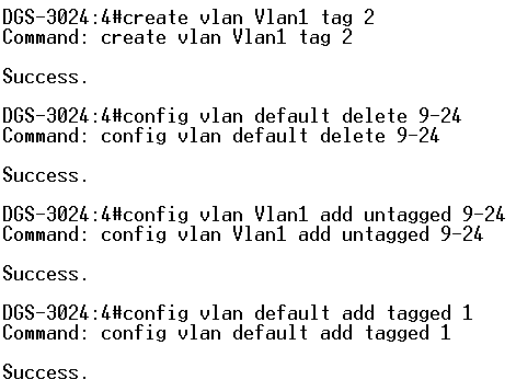
Step 1:From command line interface of DGS-3024:
DGS-3024# create vlan Vlan1 tag 2
DGS-3024# config vlan default delete 9-24
DGS-3024# config vlan Vlan1 add untagged 9-24
DGS-3024# config vlan default add tagged 1
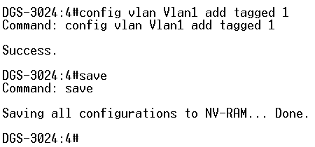
DGS-3024# config vlan Vlan1 add tagged 1
DGS-3024# save
Setup of DFL-210
Step 1: Click on Objects and Interface Address. Add New IP address for the following:
VLAN1: 192.168.2.1
VLAN2: 192.168.3.1
VLAN1_net: 192.168.2.0/24
VLAN2_net: 192.168.3.0/24
Step 2: Click on Interfaces and VLAN. Add New VLAN.
Name: VLAN1
Interface: lan
VLAN ID: 1
IP Address: VLAN1
Network: VLAN1_Net
Default Gateway: None
Click OK.
Step 3: Click on Interfaces and VLAN. Add New VLAN.
Name: VLAN2
Interface: lan
VLAN ID: 2
IP Address: VLAN2
Network: VLAN2_Net
Default Gateway: None
Click OK.
Step 4: Click on Objects and Interface Address. Add New IP4 group.
Name: All_Internal_Nets
Select: lannet, VLAN1_net, VLAN2_net
Click OK.
Step 5: Click on Interfaces and select Interface Groups. Add New Interface Group.
Name: All_Internal_Interfaces
Select: lan, Vlan1, Vlan2
Click OK.
Step 6: Click on Rules, IP Rules, Lan to WAN. Edit The following 4 Rules:
drop_smb-all
Allow_ping-outbound
Allow_ftp-passthrough
Allow_standard
Note: Each of the rules will need to be edited and have the new interface/nets applied.
Step 6: Click on Rules, IP Rules. Add New IP Folder (Optional).
Name: Vlan_Rules
Click OK.
Step 7: Add new IP Rule.
Name: Allow_VLAN1_to_VLAN2
Action: Allow
Service: All Services
Schedule: None
Source Interface: VLAN1
Source Network: VLAN1_Net
Destination Interface: VLAN2
Destination Network: VLAN2_Net
Step 7: Click Configuration Tab and click Save and Activate.